What are you looking for?

oponeo.de

The feasibility of the bridge-vehicle concept was checked with some development steps

The example of a bus was used to show how the most important components of a vehicle should be put together in a modular way so that the widest possible range of different vehicles can be designed with the same "biotopic" framework conditions without having to develop each vehicle individually. Some components, such as the vehicle frame or the wheel assembly, were analysed in detail, while standard solutions were used for others. The development of the bridge fleet is thus in line with the current trend in the automotive industry: different existing models are no longer incrementally optimized, but the vehicles are "rethought".

Content: Three aspects of vehicle development were examined in more detail - FEM, modularity and design or powertrain simulation.

With the help of the Finite Element Method (FEM) and a load case assumed especially for the "bridge section biotope", the frame design was carried out for the conceived masses as well as their applied points of application.


The efficiency and space advantages resulting from the biotope character and the modular design were exemplified by the wheel assembly.


A powertrain simulation was developed in order to be able to make a statement about the technical key data of the electric motors, the associated transmissions and the energetic load profiles of (buffer) batteries. For the present concept, numerous input parameters such as vehicle mass, maximum speed, driving resistance, etc. were determined, which enabled a reliable calculation of the required output variables.

Optimized weight distribution for all components of a vehicle means less drive energy required

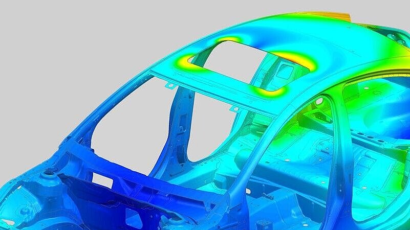
The vehicle fleet on the bridges is manufactured in lightweight construction. In order to make all components as light as possible, the loads on numerous components are determined using the finite element method. In this way, structures are manufactured that are designed in such a way that they can absorb the forces that occur, but no material is unnecessarily wasted. The result is specialized parts that are nearly ideal for their respective application and thus very light.

92 zielteck.co

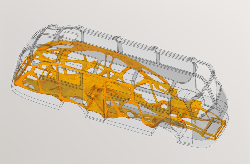
The Neoplan NH 6/7 is one of the larger vehicles on the bridges: Topology optimization was carried out for it

A topology optimization was carried out for the concept of the frame structure.

Within the available installation space, an organically acting structure is created here, which, depending on the load and bearing, suggests optimal force flows.

Even if such a structure cannot be finished directly, it provides valuable information for the actual design. This should then have an optimum ratio of weight to strength or stiffness.

In the early concept phase, the focus was on innovative methods

In order to be able to adapt the resulting concept perfectly to the conditions of the bridges, it was optimized using the finite element method (FEM).

In this process, specific load cases are considered that reflect cyclic - i.e. everyday - loads on the one hand and extreme cases such as collisions on the other.

With the aid of the FEM, the frame was developed to be stable and weight-saving. In this way, safety and load-bearing capacity can be guaranteed despite the lightweight construction.

Stiftung Altes Neuland Frankfurt GNU

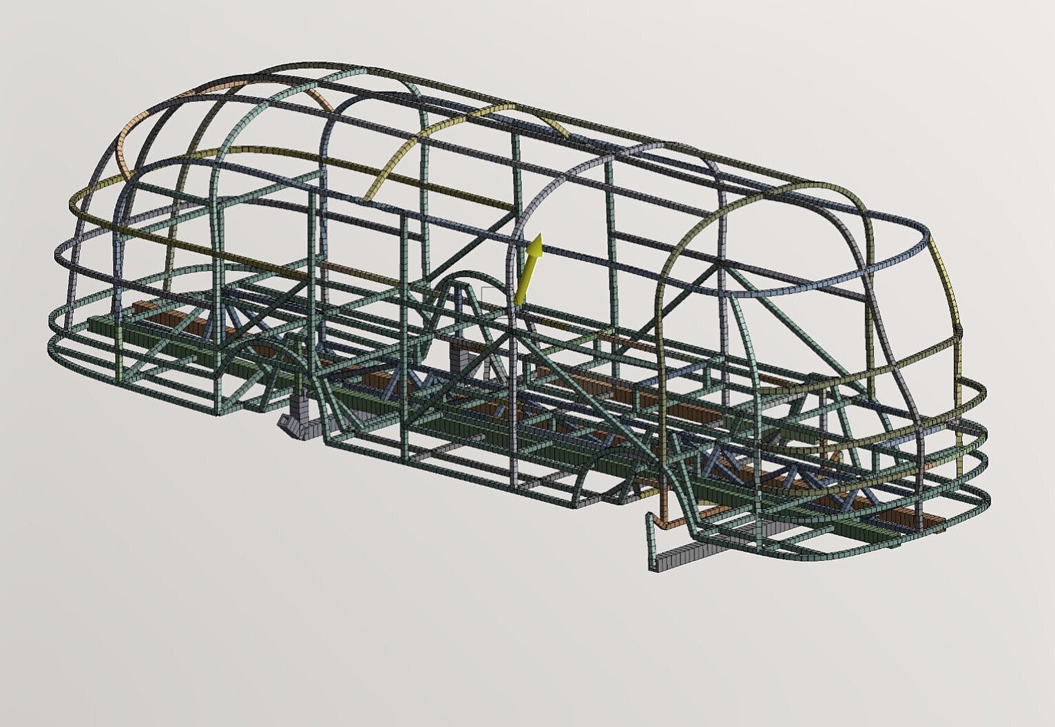
For the design of the frame structure, a simple beam model was used for the FEM analysis. This offers the advantage that changes can be easily incorporated during the development phase and the calculation time is much shorter compared to a detailed 3D model.

The requirements for the frame of the bridge Neoplan NH 6/7 were defined

The frame of a vehicle consists of rectangular steel or aluminum profiles. These are bent and welded in certain shapes so that the frame is resistant to various forces.
The forces acting in the frame structure result from the accelerations and point masses.

The masses represent relevant components in the interior, such as various aggregates and tanks, but also passengers, seat benches and also windows and trim panels.

The point masses (represented as spheres) are attached to the frame as realistically as possible using 1D elements. In this way, the resulting forces and moments are correctly represented.

This model can also be used to simulate the deformation of the frame under load.

Stiftung Altes Neuland Frankfurt GNU

All masses, such as seats, tanks or even the planking and glazing, were represented as point masses (spheres) and connected to the frame structure.

All connections have been taken into account in the frame structure of the bridge neoplan

This connection is shown as an example for the driver's seat and another seat.

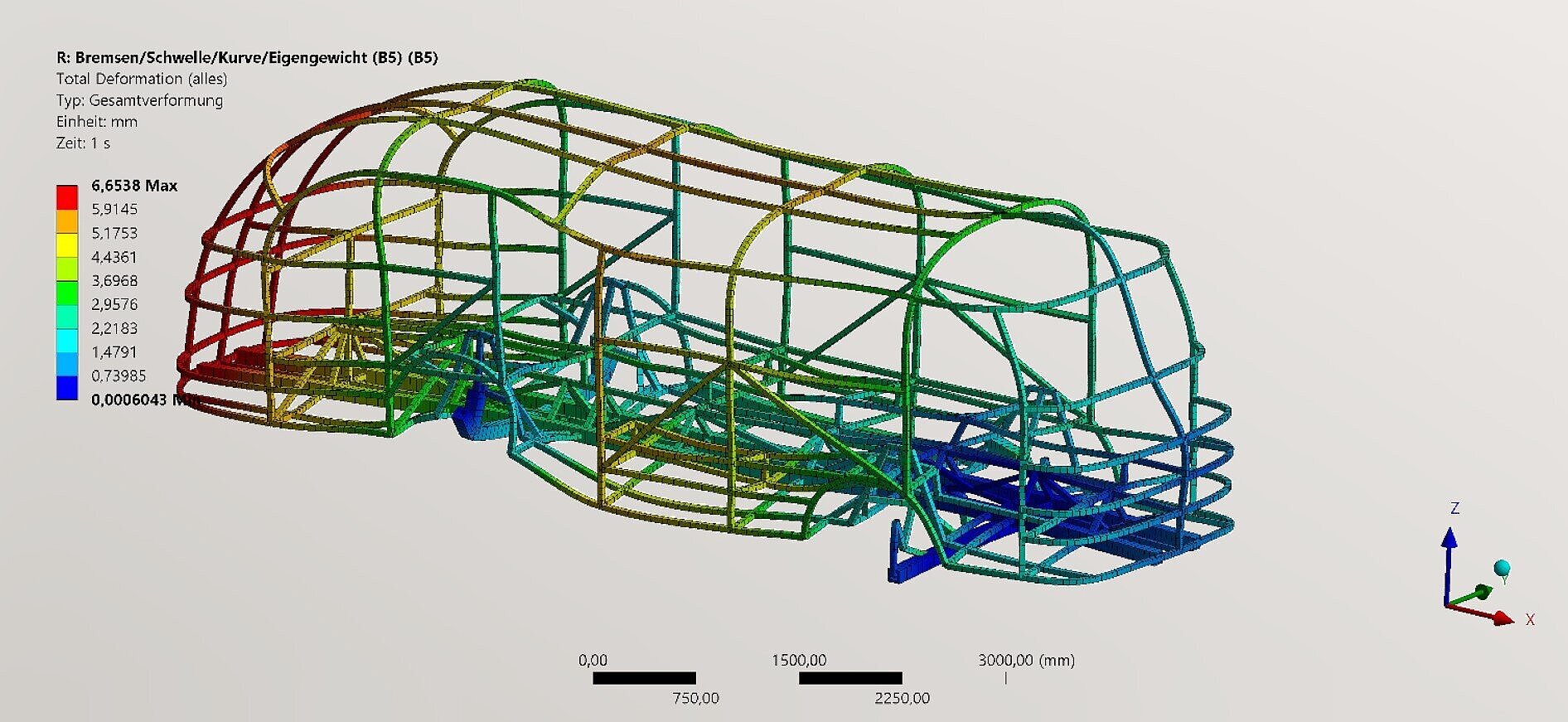
The load case under consideration involves a combination of quasi-static loads due to braking, sleeper crossing, pothole crossing, cornering and dead weight

A rocker was designed for the bearings of the frame structure on the front axle. Together with the bearings on the rear axle, this provides the most accurate kinematics possible.

The kinematics of the chassis were also realized using joints. The cross-sections of the individual beam elements were parameterized. In this way, it was possible to achieve as uniform a degree of utilization as possible over many iterations.

Frame structure - calculation results of maximum deformation

The maximum deformation that occurs under the described load case is shown here. However, the degree of utilization of the structure is primarily relevant. The degree of utilization is determined via a program code with analytical formulas. This is based on the FKM guideline.

Stiftung Altes Neuland Frankfurt GNU

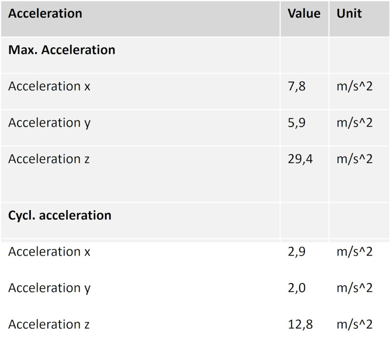
Acceleration values for the design of the Neoplan NH 6/7

Since the vehicle moves in a three-dimensional world, it also experiences accelerations in all spatial directions.

If the vehicle is slowed or accelerated suddenly, the frame must withstand these forces.

Here, there are accelerations that occur regularly, i.e. during everyday operation, and those that occur rarely, mainly in emergency situations. Both were considered in different ways.

Altes Neuland Frankfurt

The modular design of the vehicles on the Frankfurt bridges enables components to be replaced quickly and easily, thus ensuring permanent modernization

With a planned service life of one hundred years, technical progress must also be taken into account.

Thanks to their modular design, the cars can be easily modernized - by simply replacing the outdated components with newer ones, without having to replace the entire vehicle. For example, the powertrain can be replaced if other types of drive become established.

Everything else about the vehicle is retained in a resource-saving manner.Last but not least, there is another important factor that contributes to the longevity of the vehicles: There will be hardly any, not to say no more accidents, as all vehicles are forward-looking on the road.

iStock-155388818

With 400 different trains, buses and cars, it is not possible to develop each vehicle individually

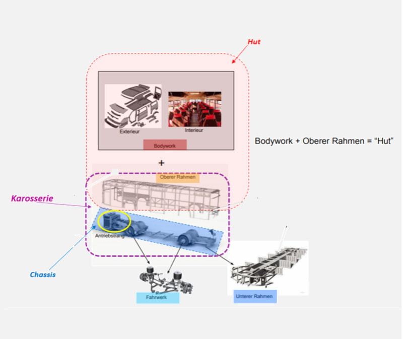
In the modular design, you have the lower frame as a component on the one hand, and the "hat" as a component on the other, which is placed on top. The interior in between can be filled with the required modular components - in the case of a hydrogen-powered vehicle, for example, these would be the fuel cell, tank, battery, chassis, electronics, and so on.

Stiftung Altes Neuland Frankfurt GNU
Stiftung Altes Neuland Frankfurt / GNU

The concept of modular components inside a vehicle creates flexibility in the external form: The future of vehicle construction?

With the modular concept, it is possible to build many variants and Oldtimer bodies (such as different vintage cars) that are the same structurally and from the internal arrangement of the technical modules: A colorful diverse fleet of vehicles is created without having to develop each vehicle from scratch.

Should the number of vehicles in cities decrease in the future due to autonomous driving becoming the norm with urban vehicle fleets, then it will become attractive for the automotive industry to rely on varied vehicle designs that are different on the outside but modular on the inside or structurally.

Stiftung Altes Neuland Frankfurt / GNU

Each vehicle consists of individual modules that can always be rearranged

A good example of modularity is the wheel suspension. Tires, suspension and axle elements are always the same for vehicles of similar weight, but are made slightly wider or narrower and placed further forward or back. The advantage: A lot of time can be spent on optimizing the space and energy efficiency of each individual module.

The modular chassis reduces the development effort and minimizes the number of different spare parts required

Almost all vehicles on the Frankfurt bridges use the same chassis concept. A portal axle with wheel hub motors is installed, which makes it possible to use a particularly large amount of space in the interior.

By using this concept in all vehicle categories, the overall system only needs to be fundamentally designed once and is then only slightly adapted for each vehicle.In addition, an all-wheel drive system, air springs and all-wheel steering ensure a pleasant and efficient driving experience.

Stiftung Altes Neuland Frankfurt GNU

The wheel assembly combines the advantages of a four-wheel drive with those of wheel hub motors

The wheel assembly concept includes so-called wheel hub motors, which are located in the wheel hub. This technology is particularly well suited to the vehicles on the Frankfurt bridges because the classic disadvantage, namely the high unsprung masses, plays only a minor role.

Thus, because of the comparatively low speeds and accelerations on the bridges and because of the low weight of the buses, much smaller and thus lighter engines are used than in conventional road transport.

In addition to lower weight, such smaller engines have another advantage: There is plenty of space in the interior for passengers because the drive is located directly on the wheel.In addition, engines in all wheels make the vehicle maximally efficient in both propulsion and braking.

Stiftung Altes Neuland Frankfurt / GNU

Air suspension ensures maximum ride comfort and adapts dynamically to the driving situation

The suspension of the vehicle is realized by air springs analogous to conventional systems in local passenger transport. This significantly increases ride comfort and reduces weight compared to steel springs. In addition, the vehicles can be lowered laterally at the stops for convenient boarding.

In addition, the spring rate can be flexibly adjusted while driving. Since the topography of the track is known and each vehicle is also permanently updated, this allows the suspension to be fine-tuned for each section and driving situation, starting from a basic setting.

Altes Neuland Frankfurt

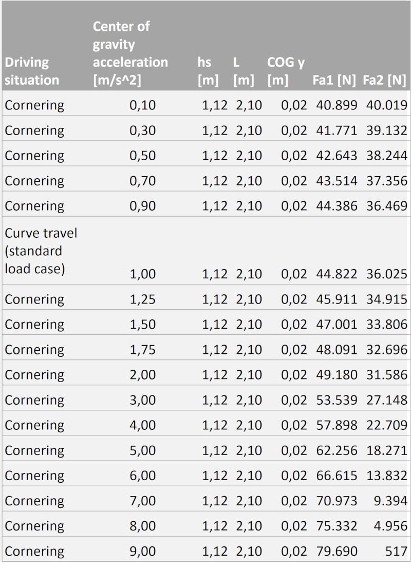
For the design of the components in the chassis and assessment of the centre of gravity position, the dynamic wheel load displacement must be determined

A dynamic wheel load shift occurs during acceleration and deceleration as well as during cornering.

With these values, the components of the chassis can be designed according to the expected loads.

In addition, it is checked whether the position of the centre of gravity, which follows from the arrangement of the components, is within a safe range. This ensures that the vehicle has sufficient grip in all driving situations and is not at risk of tipping over in curves.

Stiftung Altes Neuland Frankfurt GNU

Gain energy while braking and still be safe on the road

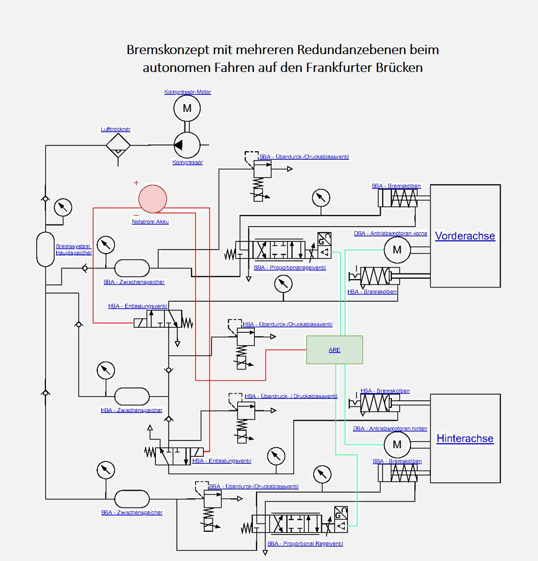
Due to the electric drive on all wheels, the vehicles do not require mechanical brakes during normal operation. This maximizes energy efficiency and minimizes wear and tear and thus maintenance.

Since this system does not work in the event of a power failure, a pneumatic-mechanical backup system is installed which automatically brakes the vehicle in this case.

Together with the concave track shape, this ensures that the vehicle is in a safe condition at all times.

Stiftung Altes Neuland Frankfurt GNU

The speed is always adjusted in such a way that passengers do not find even tight curves nauseous

When driving a car on curvy roads, some people quickly become nauseous. This happens because the driver of the vehicle enters the bend at high speed or accelerates when leaving the bend.


The occupants thereby experience a high, so-called lateral acceleration. Experience shows that passengers in conventional local passenger transport are exposed to maximum lateral accelerations of approx. 2.0 - to 2.5 m/s^2.


On the Frankfurt Bridges, the autonomous system optimizes the speed of the vehicles in the curves so that the lateral acceleration is always below 1.5 m/s^2. This is possible without any special effort because the system knows the exact nature of all curves.

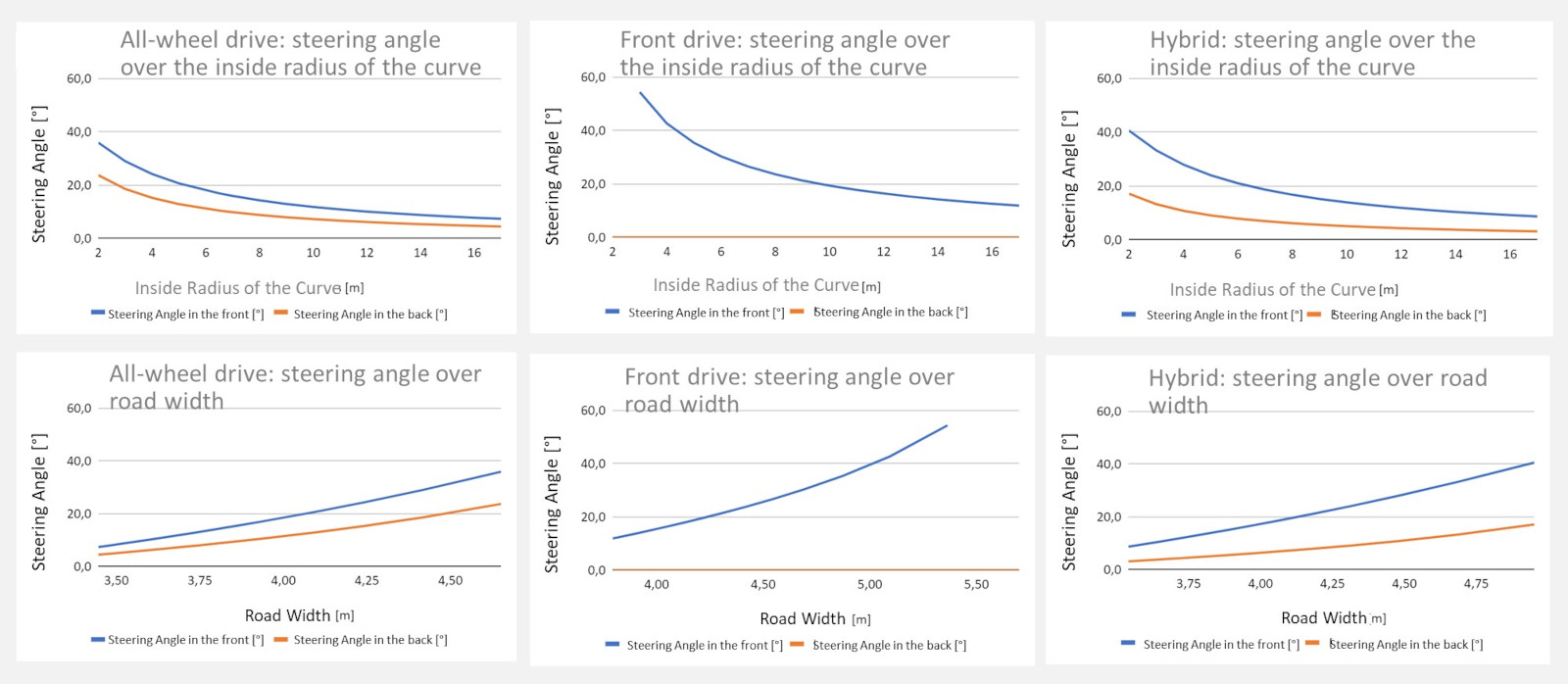
In order to use all advantages of possible steering concepts for the best possible and space-saving route on the Frankfurt bridges, different steering concepts were compared

Typically, vehicles are steered by steering the front axle. However, it is also possible to steer the rear axle in order to negotiate tighter and narrower bends. For maximum driving comfort and ease of steering, vehicles use hybrid steering, which has a steering ratio of 0.7 between the front and rear axles. The influences of the steering angle on the inside radius of the bend and the width of the road are shown graphically for the individual steering concepts.

Stiftung Altes Neuland Frankfurt GNU

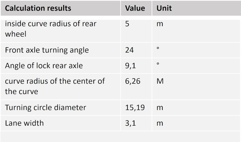
To plan the route on the Frankfurt Bridges, the dimensions of the towing curve of the largest vehicle were first calculated

For a large vehicle to be able to drive around a curve, it must not be too narrow or too tight. For this reason, the towing curves of the largest vehicles on the Frankfurt bridges were determined precisely using geometric relationships. Not only the wheelbase but also the front and rear overhangs are relevant here. The data shown are valid for the Neoplan NH 6/7 model, which has the largest vehicle dimensions.

Stiftung Altes Neuland Frankfurt GNU

The route on the Frankfurt Bridges was planned according to the towing curves of the largest vehicles

When planning the route, the radii and widths of the curves were created digitally and compared with the calculation results to ensure that the route is suitable for all vehicles.

Stiftung Altes Neuland Frankfurt GNU

The average speed of vehicles on the Frankfurt bridges is significantly influenced by the curve radii of the route.

Stiftung Altes Neuland Frankfurt GNU

As part of the route development, the maximum speed at which the vehicles can drive through the curve was calculated. For this purpose, the tightest radii of numerous curves on the planned route were measured and calculated with the maximum permitted lateral acceleration.

The course of the track in vertical direction also has a great influence on the dimensioning of the components and was taken into account in the simulation.

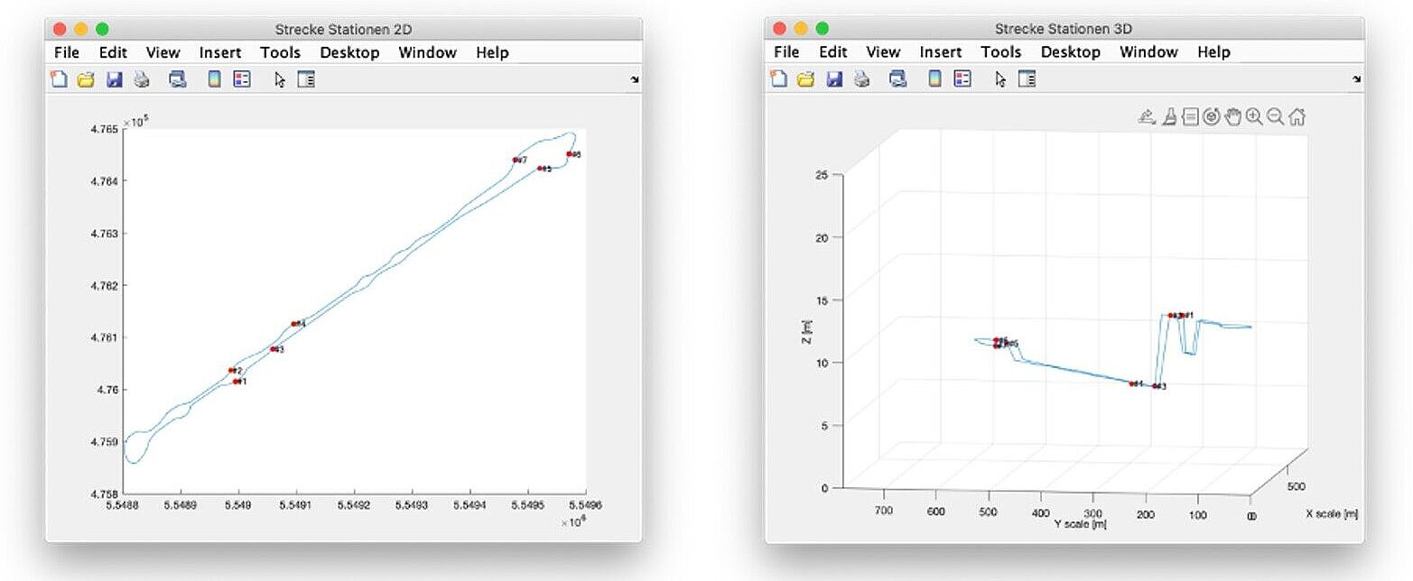
The raw data of the route planning, consist of two-dimensional points along the route and the information, at which of these points stations are located. These raw data must first be processed into usable route data, for which some scripts have been programmed.

The procedure is demonstrated below using Kennedyallee as an example. In order to create a circular route, points at Türmchenplatz, in particular the indicated arbe to Stresemannallee, as well as Kennedyallee further to the north-east were first removed. In addition, the route must be closed at the southwestern end. For this purpose, a semicircle can be used, which tangentially connects to the end points. However, this would result in a circle with a radius of only 4.4 meters, which is not consistent with the drivable radii of the vehicles. For this reason, the circuit is closed manually by two S-curves and a semicircle with a larger radius.

Stiftung Altes Neuland Frankfurt GNU

The course of the track in vertical direction also has a great influence on the dimensioning of the components and was taken into account in the simulation.

Since the route runs in the real world, not only two-dimensional coordinates have to be included in the route planning, but also the respective height of a point above sea level. On their way through Frankfurt, the vehicles have to drive up and down various inclines. The height data of these inclines are derived from the height profile of the ground and the bridge itself.

Stiftung Altes Neuland Frankfurt GNU

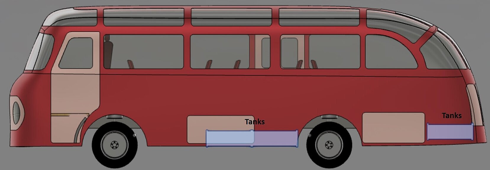
Due to the modular design, low centers of gravity can always be implemented for different models

The positioning of all components in the vehicle determines the center of gravity and thus also the driving dynamics. To ensure that the vehicles "lie on the track" as well as possible, all components were placed as far down as possible.

This keeps the vehicle from swaying as much as possible in curves and prevents it from tipping over.  Many components can be arranged in a modular fashion to optimize driving dynamics.

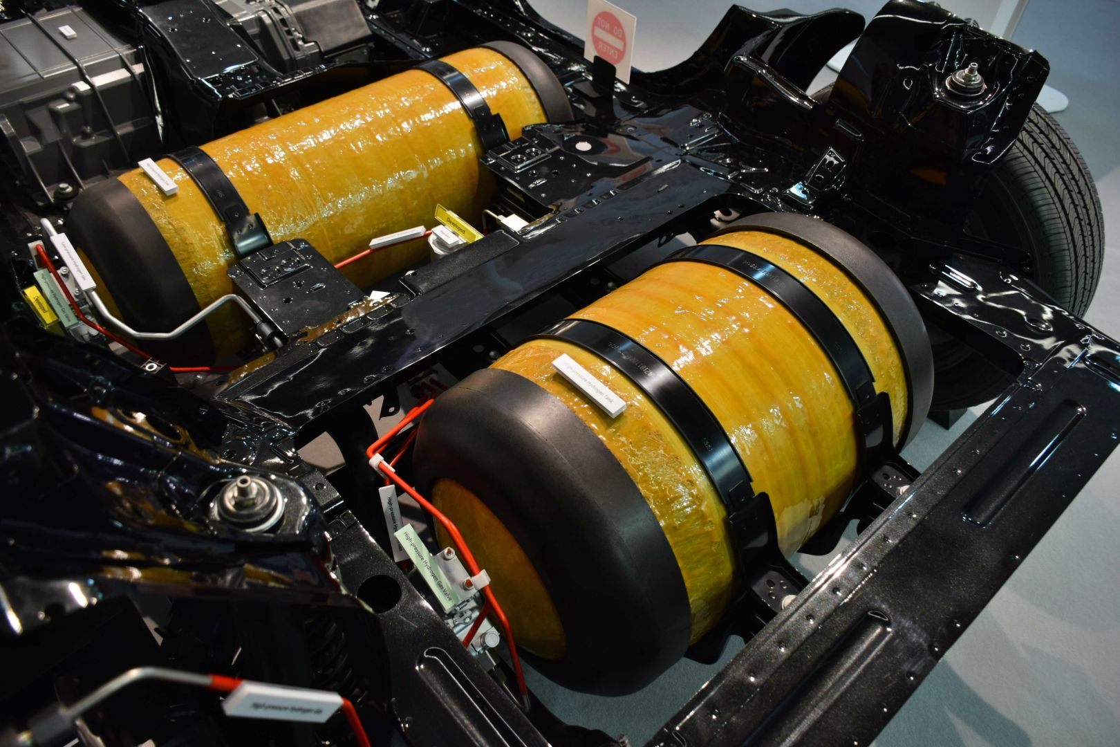
Hydrogen tanks (blue), for example, are heavy and are housed in the double floor of the vehicle wherever possible. Large parts of the frame structure are also located there.

Stiftung Altes Neuland Frankfurt GNU

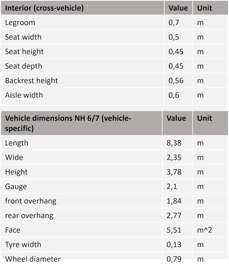
Every design and every simulation calculation requires boundary conditions and parameters

In order to make all design processes and calculations carried out as part of the concept as transparent as possible, all calculation assumptions and values were recorded in parameter lists.  

Here there is a vehicle-specific parameter list, which contains all values that can be specifically assigned to a vehicle or that differ between different vehicles.  

In addition, the cross-vehicle parameter list contains all values and boundary conditions that are valid across different vehicles.

On the left side, some cross-vehicle requirement values for the interior as well as the vehicle-specific dimensions of the Neoplan NH 6/7 are shown as examples.

Stiftung Altes Neuland Frankfurt GNU

The design of electric motors, batteries and hydrogen tanks is made possible by complex powertrain simulation

If one wants to make a statement about the required electric motors, batteries and hydrogen tanks, a simple consideration of the influencing variables is no longer sufficient, since the effects resulting from these variables cannot be determined immediately and can also change again and again.

For this reason, a complex simulation was developed into which the vehicle parameters such as external dimensions and weight are fed. In addition, the simulation knows all the necessary parameters of the route on the bridges, including gradient areas, stop waiting times, curves, etc.....  

From this, if physical laws are applied correctly, forces can then be determined, which in turn can be converted into torques and power specifications of motors. In addition, the load profile of batteries and fuel cells can also be determined and hydrogen tanks can be dimensioned.

Stiftung Altes Neuland Frankfurt GNU

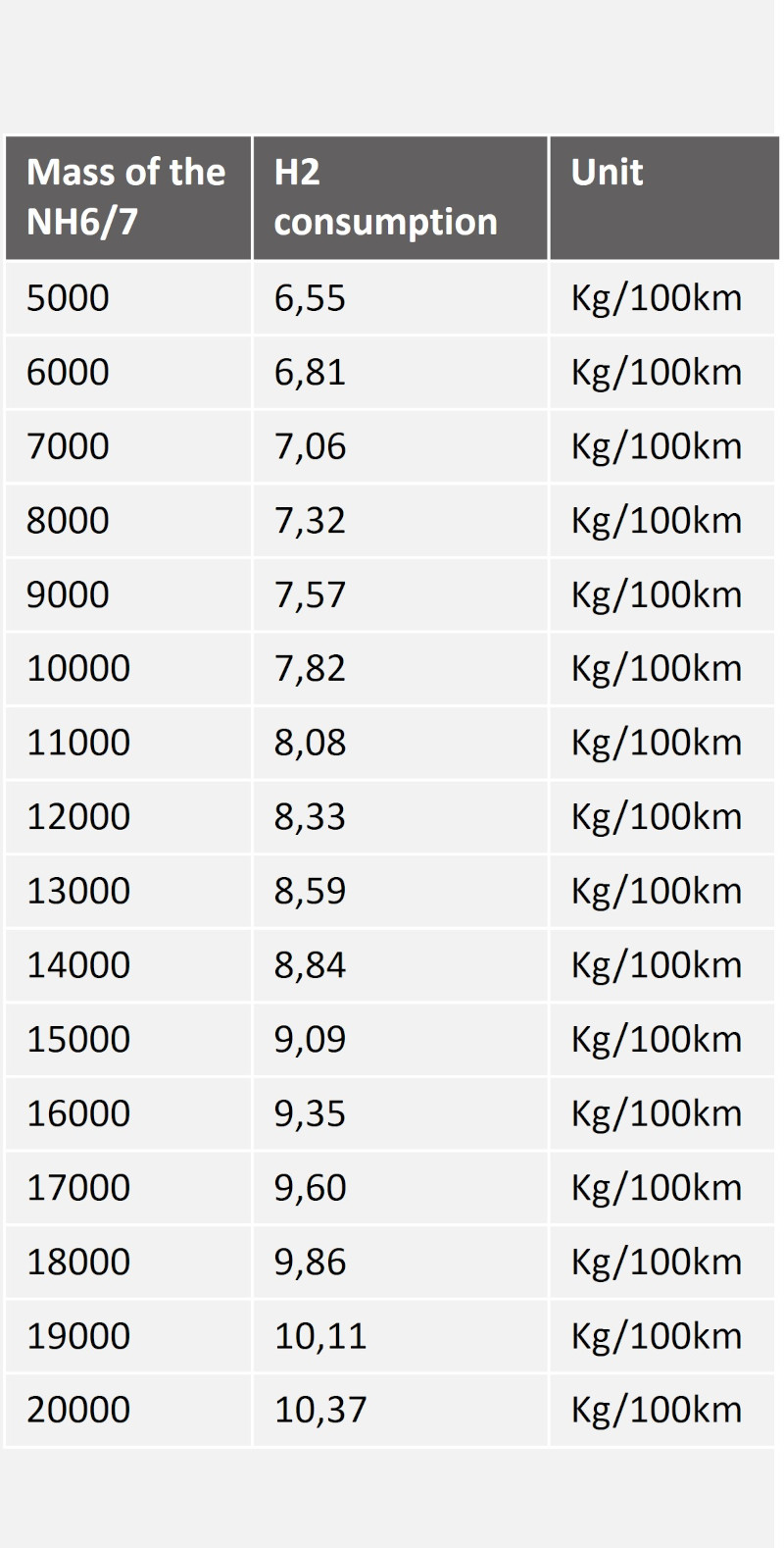
It is not only the installed drive components that influence energy consumption when driving, but also the weight. This results from the size of the engines, tanks and batteries.

In addition to the efficiency of the installed components, the weight of the entire vehicle is also decisive for the energy consumption and the further design of the vehicle.

In order to be able to quantitatively estimate the influence of the total vehicle weight on parameters such as energy consumption, engine torque and tank capacity, a corresponding analysis was carried out.

This shows that if the reference mass is changed from 10 t to 5 t, a reduction in hydrogen consumption in kg per 100 km from 7.82 to 6.55 can be achieved. Therefore, all vehicles should be designed in lightweight construction. This was done once as an example during the concept development for the vintage bus "Neoplan NH 6/7".

Stiftung Altes Neuland Frankfurt GNU

Drivetrain simulation allows both the wheel hub motors and the transmission to be designed

Engine speed, torque and other parameters can be determined on the basis of the powertrain simulation. Depending on the available components, suitable engines and transmissions can then be selected from the state of the art.

The powertrain simulation allows the hydrogen consumption to be determined in advance and the hydrogen tank size to be specified.

The results from the powertrain simulation can be used to determine the hydrogen consumption per vehicle while driving along the route. Based on a specified operating time until refuelling or a certain number of kilometres, the required hydrogen tank size can thus be determined on a vehicle-specific basis. The vehicles on the bridges can drive for about 10 hours with their respective hydrogen tanks without having to refuel.  The vehicles on the Frankfurt bridges use hydrogen tanks with a pressure level of 700 bar. This means that significantly more hydrogen can be stored in the same volume than with 350 bar systems.

Tramino - istockphoto.com

For example, the approximate load profile of the buffer batteries of hydrogen vehicles was virtually determined by the powertrain simulation

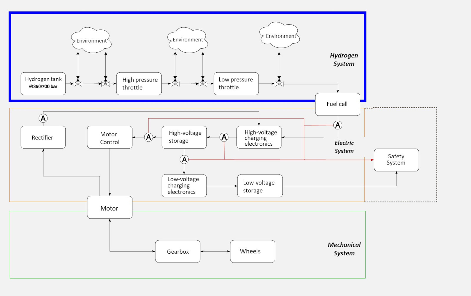
While the drive energy for battery-electric vehicles is taken from the battery while driving, hydrogen-electric vehicles are supplied by a fuel cell. This converts the hydrogen from the tank and air into electrical energy and water during the journey.  

In the powertrain simulation, a curve was determined using the example of the Neoplan NH 6/7, which indicates how much energy is required for which section of the route. For example, when a vehicle is driving uphill, there is a strong headwind and there are many passengers with heavy luggage in the passenger compartment, it requires a particularly large amount of energy.

Since a vehicle sometimes briefly consumes more energy than the fuel cell in the passenger compartment can supply, a small buffer battery is used that can provide this additional amount of energy. In this way, the fuel cell can be chosen to be as small as possible and as large as necessary.  If the vehicle consumes little energy, for example because it is driving downhill, the excess power of the fuel cell is used to recharge the battery.

The buffer battery consists of two components

If the charging and discharging processes during the journey are analysed in more detail using the so-called rainflow algorithm, it becomes clear that a lot of energy is usually only released for a short time. In order to be able to make a decision as to which battery technology makes sense, certain boundary conditions must be taken into account.

In lithium-ion batteries, for example, a certain amount of energy can be extracted until the battery cell dies due to age or cycling. If the cycles are relatively small, more energy can be extracted overall than if, for example, the battery is always fully discharged. However, if the cycles are very small, the battery is constantly "hardly" loaded, which reduces the service life, although the capacity of the battery is not used sensibly.

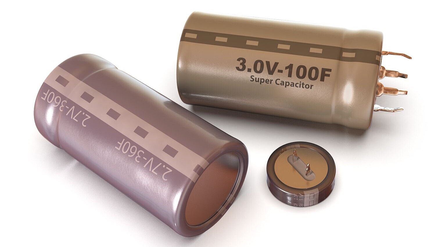
Since the focus of the development concept is also on the longevity of the components, a combined energy storage concept is proposed for the "buffer battery": Very small cycles are handled via supercapacitors so that the battery is not loaded. Larger cycles are realized via the battery.  In this way, the lifetime of the buffer battery is maximized and limited mainly by the aging of the battery cells over time.

celsopupo - istockphoto.com
coddy - istockphoto.com

The results of the powertrain simulation also make it possible to easily specify engine and transmission characteristics

Stiftung Altes Neuland Frankfurt GNU

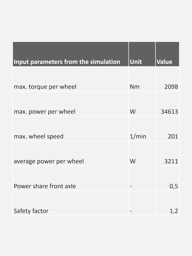
The specifications of the engines as well as the transmission were determined for the example vehicle Neoplan NH 6/7 based on the results of the powertrain simulation. First and foremost, parameters such as the maximum torque per wheel, the maximum power per wheel and the maximum speed are taken into account.

 These parameters are calculated with a safety factor and then result in the minimum requirements for the motor to be selected. In the next step, the performance data of various motors available on the market were researched and compared with the calculated requirements. If all requirements are met, the motor is considered suitable.

Based on the calculations, a suitable motor model was selected as an example

The gear ratio must also be determined in coordination with the engine characteristics.

The minimum permitted gear ratio is determined by the required torque, while the maximum permitted gear ratio is determined by the required speed.

The gear ratio of the selected gearbox must lie between these two values.

Stiftung Altes Neuland Frankfurt GNU

The energy consumption of a vehicle on the Frankfurt Bridges is strongly influenced by the air conditioning performance

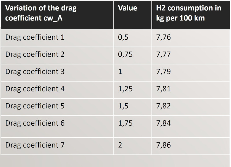
Because of the lower driving speed, air resistance, for example, is of very little importance for energy consumption when driving, but air conditioning performance is of high importance. Therefore, special glasses were provided that can significantly reduce energy consumption. An excerpt from the analysis of what effects changes in a vehicle's air resistance have on, for example, hydrogen consumption can be found below.

The table shows the effect of a change in air resistance on hydrogen consumption in kg per 100 km.

This clearly shows that air resistance has a negligible influence on consumption for vehicles on the Frankfurt Bridges.

Stiftung Altes Neuland Frankfurt GNU

Therefore, even a "simple" component, such as the air conditioning system, must be designed

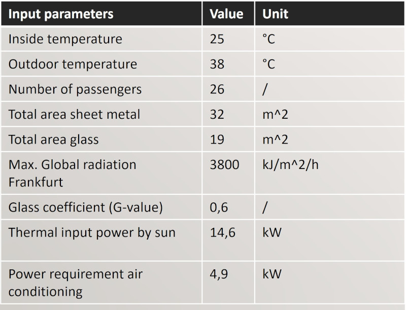
Many different factors must be considered when designing components. The more boundary conditions there are, the more difficult it is to select a correct component. For example, in order to be able to make a statement about the required air conditioning system, the solar radiation in Frankfurt, the expected specifications of the glass in the vehicle, the associated surfaces and the heat emitted by passengers were determined.

From this, the heat that is introduced into the vehicle and thus the required air conditioning output can be determined. In addition, the air conditioning output can be reduced by using modern materials.

Various parameters are included in the air conditioning design. Examples of these are the sheet metal and glass surfaces of the vehicle as well as the insulation values of the installed glass and insulating materials.

The required thermal cooling capacity can be determined on the basis of the number of passengers, the outside and inside temperatures in the vehicle and the door opening time.

By using modern heat pump technology, the electrical energy consumption can be reduced to about one third of the required cooling capacity.

Stiftung Altes Neuland Frankfurt GNU

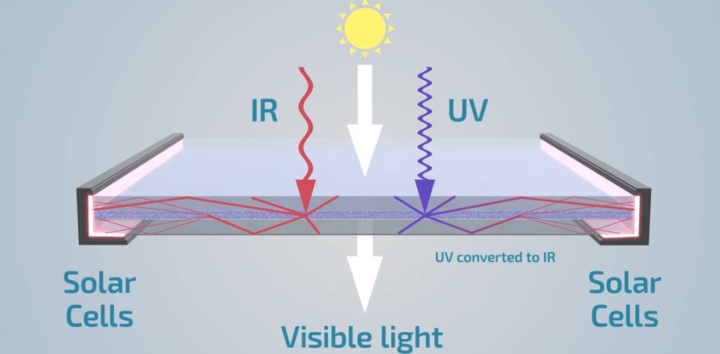
Wave guiding can reduce the air conditioning output and generate energy at the same time

ClearVue.com

Beautiful, large panoramic windows, for example, no longer necessarily represent interiors that are too hot in summer or overloaded air conditioning systems. Rather, the surfaces can be equipped with wave-guiding glass, which reduces the amount of heat entering the vehicle, reduces the amount of energy used by the air conditioning system, and generates energy along the way. To name just one of the many optimization possibilities of the present.

In this way, the old-timers on Frankfurt's bridges are equipped on the outside with the aesthetics of the past and "on the inside" with the most modern technology of our time.

Conclusion: The modular development strategy makes it possible to build up a large fleet of the most varied vehicle models with comparatively little effort.

On the Frankfurt bridges, comparatively few vehicles are needed for the required transport performance. Accordingly, more effort can be invested in the quality, durability and design per vehicle. 

Externally, the bridge fleet consists of solitaires, both in the group of buses and trains and in that of passenger cars. Technically, however, modular development within these categories means that each vehicle does not have to be developed individually, but can be built modularly with only minor adaptations.